
Geometry nodes are an incredible Blender feature, but did you know Blender's Python API also lets you script geometry nodes just like any other data block?
You can create nodes, set their parameters, and connect them programmatically, opening the door to automated scene generation, custom tools, and rapid model prototyping with just a few lines of code instead of manually wiring dozens of nodes.
In this tutorial, you'll learn how to create geometry node setups entirely from a Python script. We'll cover the full process from building a new node tree to assigning it to an object with clear examples you can paste directly into Blender's scripting editor.
In case you missed it, have a look at our introduction to Blender scripting first.
Why Script Geometry Nodes?
Blender's Geometry Nodes editor is an excellent visual system for building procedural tools: it's intuitive, flexible, and great for experimentation once you get the hang of it. But as projects grow in complexity, manually managing large node networks can become tedious and difficult to maintain, especially if you need to reuse them throughout many 3D modeling pipelines.
Scripting allows you to generate, modify, and connect nodes automatically. Instead of manually recreating the same setups across multiple projects, you can write a script once and reuse it whenever you need it to save time or make your animations more consistent.
A scripted node setup isn't tied to a single .blend file: it can be stored, versioned, and shared just like any other piece of code. This makes it easy to build a library of procedural tools that can be reused across different projects or shared with other artists and developers.
Let's see how scripting works in practice with a few code snippets.
You can find the complete source code for the example integration showcased in this guide on our GitHub:
🔗 https://github.com/cgwire/blender-scripting-geometry-nodes
1. Creating a New Node Tree
Every Geometry Nodes setup starts as a node tree, which stores nodes and their connections. You can create one from Python using Blender's data API:
import bpy

node_tree = bpy.data.node_groups.new("MyGeoNodesTree", 'GeometryNodeTree')
You can think of this node_tree as the digital canvas that will hold all your procedural logic. Once created, you can add nodes, connect them, and set their properties like in Blender's graphical user interface.
2. Add Nodes and Connect Them
Next, let's add a few basic nodes. We'll create an Input Geometry node, a Subdivision Surface node, and a Group Output node, then connect them and apply the result to our cube.
# ADD NODES
geo_input = node_tree.interface.new_socket(
    name="Geometry",
    in_out='INPUT',
    socket_type='NodeSocketGeometry'
)
geo_output = node_tree.interface.new_socket(
    name="Geometry",
    in_out='OUTPUT',
    socket_type='NodeSocketGeometry'
)

input_node = node_tree.nodes.new("NodeGroupInput")
subdivide_node = node_tree.nodes.new("GeometryNodeSubdivideMesh")
output_node = node_tree.nodes.new("NodeGroupOutput")

input_node.location = (-300, 0)
subdivide_node.location = (0, 0)
output_node.location = (300, 0)

# LINK NODES
node_tree.links.new(input_node.outputs['Geometry'], subdivide_node.inputs['Mesh'])
node_tree.links.new(subdivide_node.outputs['Mesh'], output_node.inputs['Geometry'])

# APPLY TO CURRENT OBJECT
obj = bpy.context.object
mod = obj.modifiers.new("MyGeoNodesModifier", "NODES")
mod.node_group = node_tree
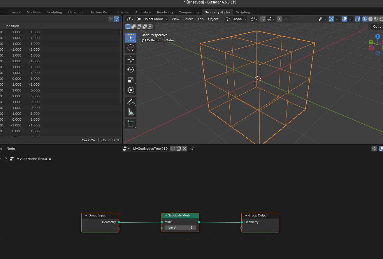
When you run this script, you'll have a functional (though simple) geometry node setup that subdivides any geometry it's applied to:
3. Set Parameters and Link Geometry to Objects
You can modify parameters directly via the node's properties. For example, let's increase the subdivision level and apply this node group to an object:
subdivide_node.inputs['Level'].default_value = 3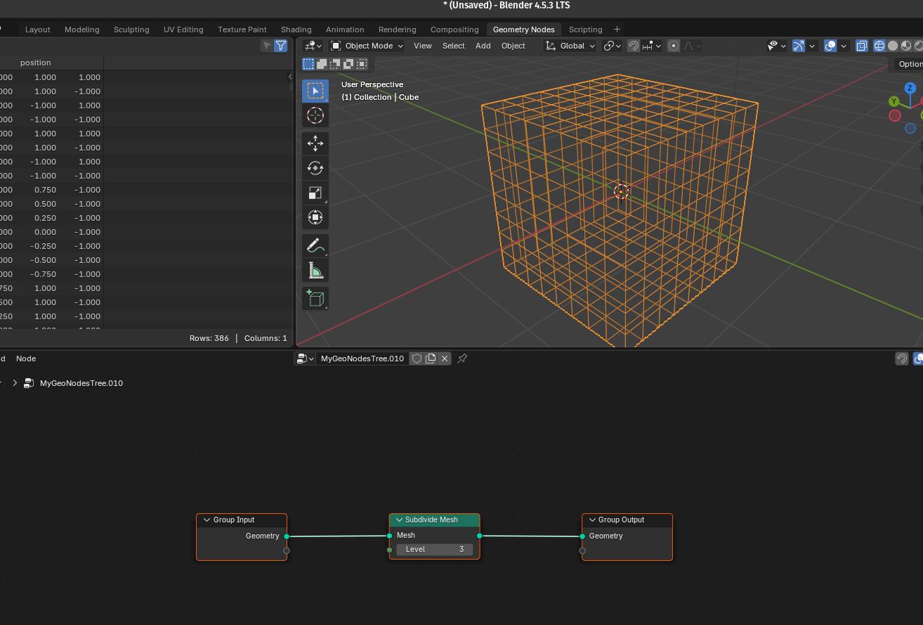
Adjusting default_value for inputs is an easy way to parameterize your setup.
For a full breakdown of the available parameters and types, refer to the official Blender Python API documentation.
4. Create a Custom “Cube Crowd Generator” Node Group Programmatically
We now know how to define geometry nodes programmatically, but what about creating reusable custom nodes?
Let's work on a new example that builds a tiny procedural system that scatters many cubes on a surface. The script creates a Geometry Nodes group that takes a surface, scatters points across it, randomly offsets those points, places a cube on each point (instances), converts the instances to real geometry, and outputs the final mesh as "Cubes".
1) Create a new node group
First, we create a new Geometry Node group in Blender named "CubeCrowdGenerator".
crowd_group = bpy.data.node_groups.new("CubeCrowdGenerator", "GeometryNodeTree")Like a function, we want to be able to attach this node to any object with a Geometry Nodes modifier later on.
2) Add group input and output nodes (UI/entry points)
We place standard input and output groups on the canvas as usual:
group_in = crowd_group.nodes.new("NodeGroupInput")
group_out = crowd_group.nodes.new("NodeGroupOutput")

group_in.location = (-600, 0)
group_out.location = (600, 0)group_inandgroup_outare the visible sockets of the node group in the Geometry Nodes editor.- The script also positions them so the graph is readable.
3) Define the group interface (what the group accepts/returns)
We need to expose an input socket named Surface where we'll plug the mesh you want to populate (e.g., a plane) and an output socket named Cubes, the resulting geometry.
interface = crowd_group.interface
interface.new_socket(name="Surface", in_out="INPUT", socket_type="NodeSocketGeometry")
interface.new_socket(name="Cubes", in_out="OUTPUT", socket_type="NodeSocketGeometry")
In practice, when you add this node group to an object, you will plug its surface (an object's original geometry) into Surface.
4) Create the internal nodes (the building blocks)
We can then work on the actual internal logic:
distribute = crowd_group.nodes.new("GeometryNodeDistributePointsOnFaces")
rand_vec = crowd_group.nodes.new("FunctionNodeRandomValue")
set_pos = crowd_group.nodes.new("GeometryNodeSetPosition")
cube = crowd_group.nodes.new("GeometryNodeMeshCube")
instance = crowd_group.nodes.new("GeometryNodeInstanceOnPoints")
realize = crowd_group.nodes.new("GeometryNodeRealizeInstances")- GeometryNodeDistributePointsOnFaces: creates points across the input surface (controls how many points, distribution).
- FunctionNodeRandomValue (Float Vector): produces a random 3D vector per point used as an offset.
- GeometryNodeSetPosition: moves each point by a vector (the random offset).
- GeometryNodeMeshCube: generates a cube mesh that will be used as the instance object.
- GeometryNodeInstanceOnPoints: places the cube on each point. It doesn't create real geometry, it's just a cheap instance of the original cube.
- GeometryNodeRealizeInstances: converts instances into actual mesh geometry so they can be output as a single mesh.
5) Configure the random vector node
We set the Random Value node to return a 3-component vector we can use to offset the generated cubes in the 3D space:
rand_vec.data_type = "FLOAT_VECTOR"
rand_vec.inputs["Min"].default_value = (-0.5, -0.5, 0.0)
rand_vec.inputs["Max"].default_value = (0.5, 0.5, 0.5)MinandMaxdefine the range for each component. For example, X will be between-0.5and0.5.- Result: each point gets a slightly different offset so cubes don't sit exactly on top of one another.
6) Node layout (UI only)
We then position the internal nodes to make them easy to understand if we want to check our workflow in Blender:
distribute.location = (-400, 0)
rand_vec.location = (-200, -200)
set_pos.location = (-100, 0)
instance.location = (100, 0)
cube.location = (-400, -200)
realize.location = (300, 0)
These location assignments only affect how the nodes are visually arranged in the node editor. They don't affect what the graph does.
7) Wire the nodes together
Finally, we define how the data flows:
links.new(group_in.outputs["Surface"], distribute.inputs["Mesh"])
links.new(distribute.outputs["Points"], set_pos.inputs["Geometry"])
links.new(rand_vec.outputs["Value"], set_pos.inputs["Offset"])
links.new(set_pos.outputs["Geometry"], instance.inputs["Points"])
links.new(cube.outputs["Mesh"], instance.inputs["Instance"])
links.new(instance.outputs["Instances"], realize.inputs["Geometry"])
links.new(realize.outputs["Geometry"], group_out.inputs["Cubes"])- Surface → DistributePointsOnFaces: the input surface (plane) is used to create scattered points.
- Points → SetPosition (Geometry): set position receives the points as geometry to be moved.
- RandomValue → SetPosition (Offset): each point gets a random vector offset.
- SetPosition → InstanceOnPoints (Points): the moved points become the anchor positions for instances.
- Cube Mesh → InstanceOnPoints (Instance): each point receives a cube instance.
- InstanceOnPoints → RealizeInstances: instances are converted to mesh geometry.
- RealizeInstances → Group Output ("Cubes"): final result is made available as the group's output.
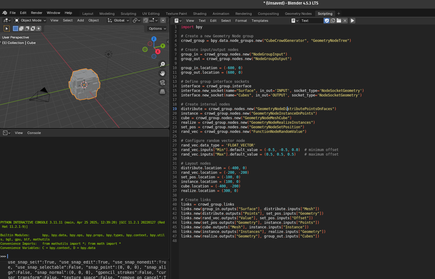
This is the full code we obtained:
import bpy
# Create a new Geometry Node group
crowd_group = bpy.data.node_groups.new("CubeCrowdGenerator", "GeometryNodeTree")
# Create input/output nodes
group_in = crowd_group.nodes.new("NodeGroupInput")
group_out = crowd_group.nodes.new("NodeGroupOutput")
group_in.location = (-600, 0)
group_out.location = (600, 0)
# Define group interface sockets
interface = crowd_group.interface
interface.new_socket(name="Surface", in_out="INPUT", socket_type="NodeSocketGeometry")
interface.new_socket(name="Cubes", in_out="OUTPUT", socket_type="NodeSocketGeometry")
# Create internal nodes
distribute = crowd_group.nodes.new("GeometryNodeDistributePointsOnFaces")
instance = crowd_group.nodes.new("GeometryNodeInstanceOnPoints")
cube = crowd_group.nodes.new("GeometryNodeMeshCube")
realize = crowd_group.nodes.new("GeometryNodeRealizeInstances")
set_pos = crowd_group.nodes.new("GeometryNodeSetPosition")
rand_vec = crowd_group.nodes.new("FunctionNodeRandomValue")
# Configure random vector node
rand_vec.data_type = "FLOAT_VECTOR"
rand_vec.inputs["Min"].default_value = (-0.5, -0.5, 0.0) # minimum offset
rand_vec.inputs["Max"].default_value = (0.5, 0.5, 0.5) # maximum offset
# Layout nodes
distribute.location = (-400, 0)
rand_vec.location = (-200, -200)
set_pos.location = (-100, 0)
instance.location = (100, 0)
cube.location = (-400, -200)
realize.location = (300, 0)
# Create links
links = crowd_group.links
links.new(group_in.outputs["Surface"], distribute.inputs["Mesh"])
links.new(distribute.outputs["Points"], set_pos.inputs["Geometry"])
links.new(rand_vec.outputs["Value"], set_pos.inputs["Offset"])
links.new(set_pos.outputs["Geometry"], instance.inputs["Points"])
links.new(cube.outputs["Mesh"], instance.inputs["Instance"])
links.new(instance.outputs["Instances"], realize.inputs["Geometry"])
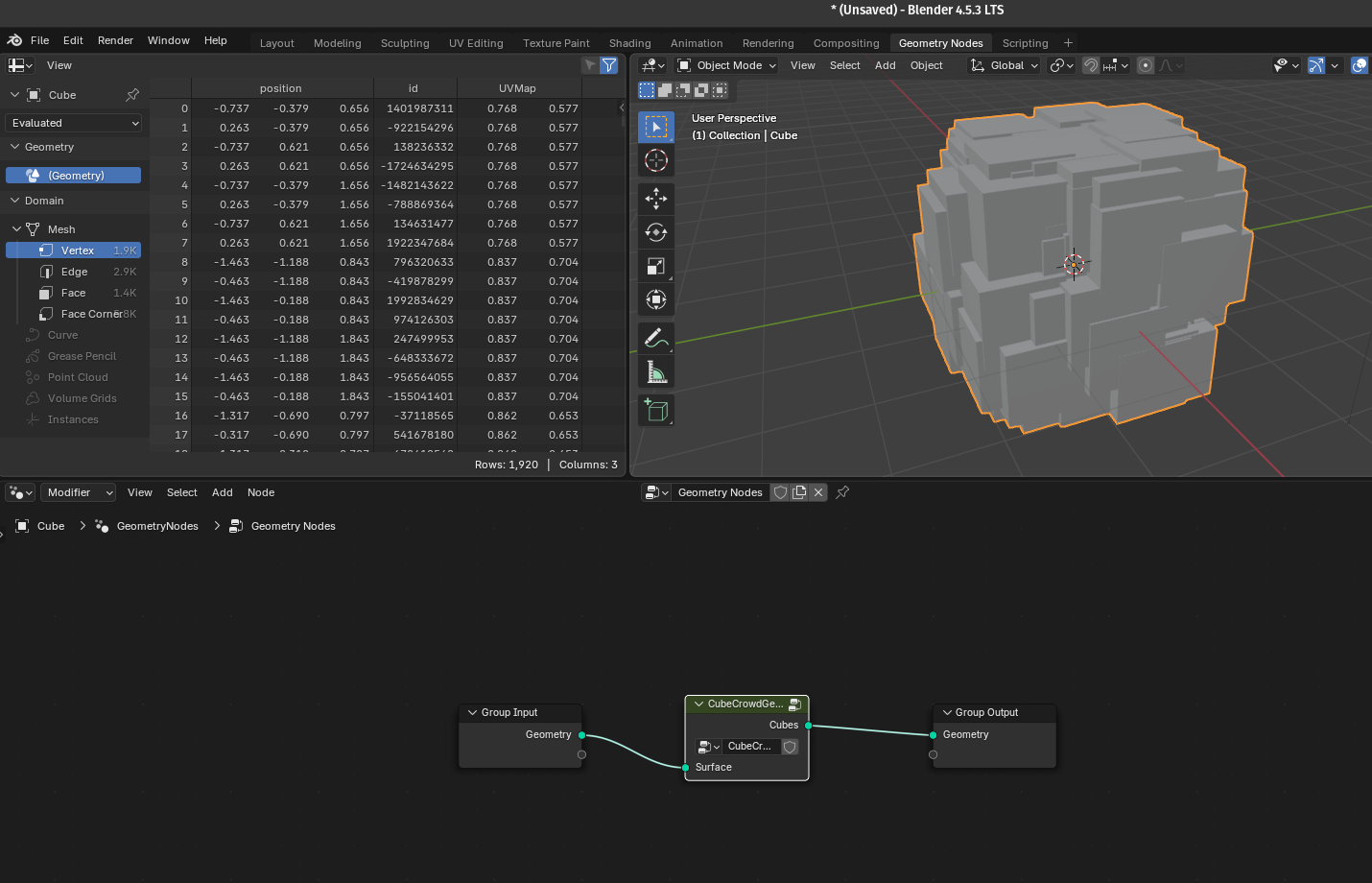
links.new(realize.outputs["Geometry"], group_out.inputs["Cubes"])Now we just copy/paste this script into the scripting workspace, run it, and we can now add our custom node from the geometry node workspace:
We can open the node group to see what's inside by double-clicking on it:
Conclusion
With just a few dozen lines of code, you can script Geometry Nodes setups that would take much longer to assemble manually. You've learned in this article how to create Geometry Node trees, add and connect nodes programmatically, control parameters and assign node trees to objects, and build a full procedural system.
Have a look at the code repository on Github to try the example yourself!

This approach unlocks endless automation potential, from tool development to generative art.


